

Installation of the FLARM- or Radio-Antenna
Please read the given hints carefully and regard them - only then the maximum range of the antennas can be reached. An old saw says: The antenna is the best high frequency amplifier - a badly installed antenna cannot be distinguished from a piece of bread.
- The maximum distance to any kind of conductive material has to be chosen. Examples of conductive materials are: metal, carbon fibres, conductive paintings, human body (water), instruments, steering rods, steel tubes (fuselage) or other antennas.
- The minimum distance to any kind of conductive materials should be minimum one wavelength from an theoretical standpoint - for the air band this means 2.4 m, for the FLARM it means 0.35 m. If this minimum distance cannot be maintained, the performance of the antennas reduced significantly and the standing wave ratio goes to bad values. In real usage for the air band antenna SuperRAnt 0.5 m had to be maintained, for both FLARM antennas SuperFAnt and FAnt 20-25 cm are a good compromise.
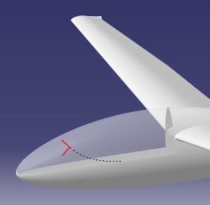
- Conductive material (also outside the minimum distance) makes a blind spot during sending / receives. The impact which can be estimated with a simple geometrical examination: lines starting from the antenna, which points on the border of the object, show the blind spot in infinity. Such blind spots have to be minimised during the installation of the antennas.
- If conductive materials are close to the antenna, the antenna leg should point perpendicular to the material instead of running parallel.
- Antennas (transponder, air band radio, FLARM...) among each other has to be mounted with distance - other antennas are for an sending / receiving antenna only a piece of conductive material. Further on, if high sending power is active, induction can take place and can destroy the final stage of other radios. This means because of the sending power in a glider mainly the radio and the transponder are critical.
- Do not roll up the feed cable of an antenna - coils are build with significant power losses. If a roll up is needed, use big diameters and do not roll it up around metal parts.
- The damping of the electromagnetic waves in a feed cable increased with the frequency of the waves. This means for the FLARM antenna the length of the feed cable should be as short as possible. Even if the mounting of an FLARM antenna in the vertical is for the performance of the antenna the damping in the feed cable dramatically reduces the complete performance of the FLARM system.
- The feeding cable should always the maximum distance to the antenna and in direct area around the antenna perpendicular to the antenna legs.
- The number of connectors in the feeding line should be as small as possible because there power losses takes place - this is especially a critical point if you use existing feeding lines for the radio.
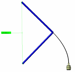
- The legs of the antenna has to be placed in straight lines. This is fundamental for the compliance of the antenna geometry - if the geometry is changed the performance of the antenna is reduced. An example is the mounting of the antenna along the inner fuselage surface. To place the antenna legs in a straight line small wood or glass(!)fibre rods can be used.
- Alternatively the shown mounting with horizontal and vertical legs is possible.
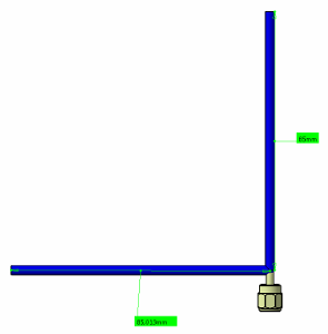
- For the FAnt or the RAnt applies: Both legs of the antenna should form a straight line and be perpendicular to the ground!
An check of the antenna installation should be done after mounting and achieved in the lifetime file of the aircraft. For the check FLARM and air band radio must be distinguished. For the FLARM please download and use the range tool directly from the FLARM homepage. It gives a good overview over the effective performance of the installation. Thereby a blind spot behind is more uncritical then one in front because the main danger comes from front because of the relative speed.
For checking the air band antenna installation a standing wave ratio measurement is the best way. Measurement devices can be ordered for about 50 Euros in the internet - attention: they have to be capable of measure up to about 140 MHz. If you never did such a measurement in the past, please ask one who did - the danger to damage your radio is cannot neglected. If you never repair the brakes of you car, you also will ask someone who know the details ...
The standing wave ratio measurement itself: a ratio above 2 has to be avoided. This means a bad sending / receiving performance and the danger to destroy the final stage of the radio. If you measure such a ratio, this can be because of:
- Mounting position of the antenna is not the best - see above
- To much connectors in the feeding cable
- Radio broken
Keep in mind: NEVER run a radio without an antenna (radio and FLRAM!)
If there are still open questions - please email.