

Crash Safety
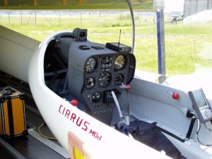
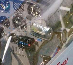
Side-view of the new instrument panel and the stiffened canopy-frame. Further on: the holder of the PDA, which is made from glas-fiber and equipped with a pull linkage so save the pilot in case of a crash from injury on this part. In many cockpits of gliders you will find holders made from metal - if the pilot survives the crash, maybe he bleed to death because of a deep injury from the PDA-holder, before help arrives ...
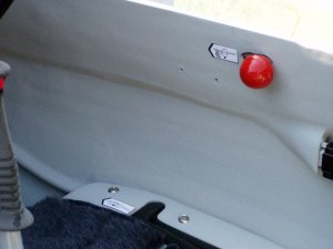
The enhancement in more detailed view.
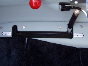
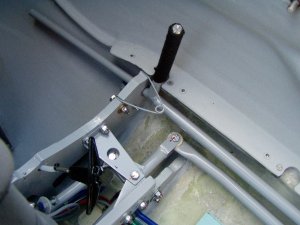
The landing-gear lever with its protection in the seat - to prevent falling whats ever inside the steering.
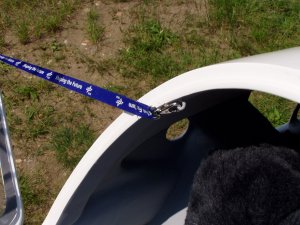
Canopy-band - including with a pull linkage for the case of jumping out of the glider.
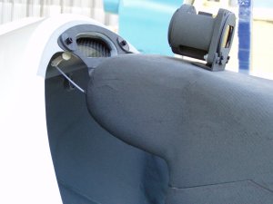
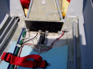
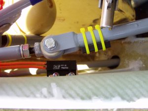
Mounting of the instrument panel at the canopy frame including the pull linkage, to allow the panel to move in front, if the pilot coming against in case of a impact.
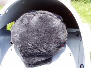
Back-rest with headrest ... real important!
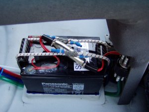
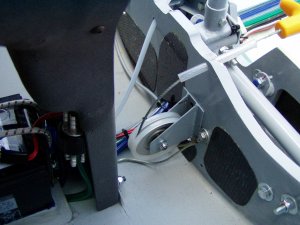
Battery and its mount. The both brackets in front and behind are made from carbon-fibres and mounted with hinges on the cockpit-floor. The elastic bands needed for the locking. The battery mount has mainly the task to sustain the forces during the flight. In case of an impact the occurring forces are that high the battery will "say good bye" flying in the front of the fuselage. Because the battery in the Cirrus is mounted in front of the instrument panel, there is no risk of hurting the pilot. Quite contrary to a mounting behind the pilot’s seat - often the batteries there are mounted with the adventuresome self-constructions and in the most cases the center of gravity of the battery lying higher that e.g. the transverse-force pipe of the wing. In case of a crash the battery will "fly around the pilots ears" ...
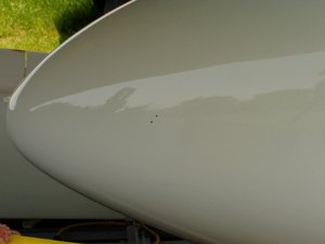
The new static-ports (the two black "fly-shits") on the fuselage. The position is calculated based on the contour of the fuselage and a CFD-code ... this ports are used for the variometers, the speed-indicator is still connected to the static ports below the wing - including its well known error.
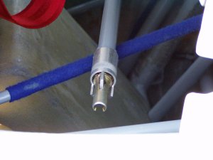
New connectors for the steering-rods in the wing including Wedekind-lockings - makes the assembly much easier.
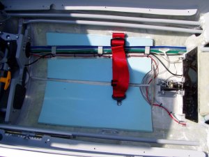
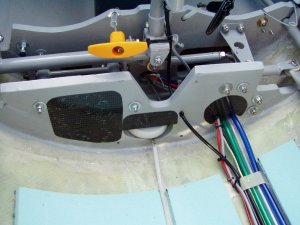
Below the seat: all cables and tubes now running on one side of the fuselage (upper side of the picture), only the bowden cable for the clutch is still in the symmetry line of the fuselage. The resulting room below the sitting-shell is now used for "ImpactFoam", which absorbs energy in case of a crash (when the ground "moves" against the sitting-shell) and helps to reduce the injury-risk for the pilot. A second ImpactFoam-pillow is used in the sitting-shell, which although can absorb energy and further on it is very comfortable on long flights. Never again pressure marks on the backside. ImpactFoam can be purchased at Segelflugbedarf24 ...
The closing of the cockpit against the landing gear build and sealed with thin carbon-fibres plates ... no water or dirt from the landing gear can invade the cockpit.
Lading-gear warning part 1: not easily to see, on the front end of the gear steering rod a switch is mounted ...
... and the second one direct on the air brake lever (here an "inductive" type of switch). There is no chance to forget the landing gear. Old pilots wisdom: there are two kinds of pilots: the first one still landed without extended landing gear (me too), the second kind pending.
All openings of the steering-frame are closed with carbon fibres plates. Why? In Australia there was an accident some time ago (Download), in which a screw-driver was fallen down during the vario compensation and fall inside the steering-frame. The pilot tried to get it back and therefore opened the strap as a really hard thermal gust hits the plane and throw the pilot through the canopy (as in a fighter plane) - thanks god he has a canopy on his back. The plane was broken after hitting the ground - and was rebuild.
The closings from the front ...
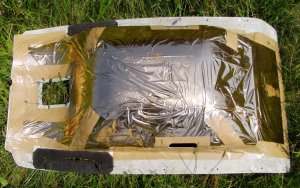
The seat from below - foam as seal for the trim lever and the landing gear lever and a rescue-foil to protect the backside of the pilot, if he is flying e.g. waves.
As in your car a rear view mirror can be helpful in your plane, especially at thermaling. Because a mounting outside the fuselage is not a good idea, the mirror has to be mounted inside the canopy.
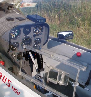
The mirror is adjusted to look on the complete tail.